
 3ds Max
 Blender
 Keyshot
 Cinema4D
 SketchUp
 Rhino
Rhino Maya/Houdini/Clarisse/Katana/

Creating Truchet Patterns in Houdini
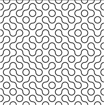
Today we are going to create a Truchet pattern. First described by Truchet in 1704, it is a decorative tiling pattern featuring non rotationally symmetric square tiles. Below is a classic example of this pattern.
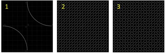
The core idea is straightforward: generate a grid array by duplicating a base tile pattern, then randomly rotate each tile unit by specific angles (90°, 180°, 270°).
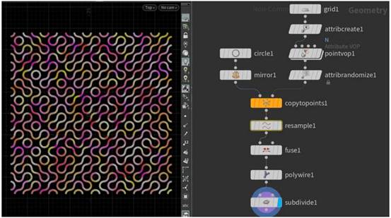
The key procedure is adding random attributes. Artists may follow different workflows, yet the underlying principles remain consistent. Below are the step by step operations.
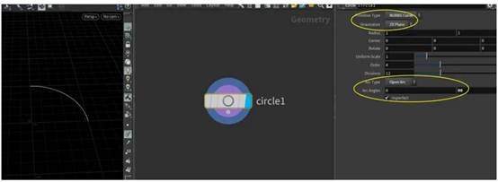
First, use the circle node to create a quarter arc curve. Set Primitive Type to NURBS Curve, and Arc Type to Open Arc. Configure Arc Angles from 0 to 90 degrees, and change Orientation to ZX Plane.
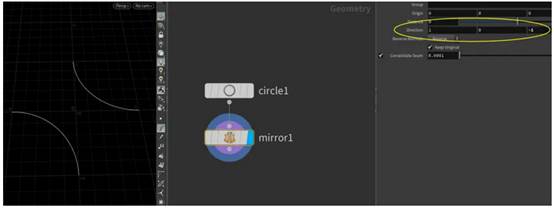
Adjust the Center parameter of the circle node to (-1, 0, 1). Next, use the mirror node for symmetrical operation, set the mirror Direction to (1, 0, -1). You will get the mirrored curve as shown below.
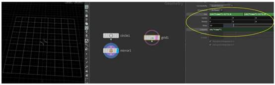
Then create a grid to serve as target points for copying. Set each grid cell to unit size 1 to match the arc radius. Adopt parameter referencing (refer to Note 004): link the Rows parameter to Columns and Size. Note that the expression for Size should be (ch("rows") 1)*2.0.
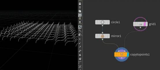
If you directly copy geometry with the copy to points node at this stage, the arcs will not orient as expected. By default, copied instances align their local Z axis toward surface normals (pointing straight upward here). This happens even without explicit N attributes, as copies default to orienting perpendicular to the plane.
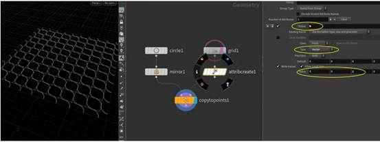
To lay arcs flat on the plane, define normals pointing along (0,0,1). Use the attribute create node: name the new attribute N, set Type to Vector, and assign the Value to (0, 0, 1) (Z axis direction).
Now we need to randomly rotate these normals within the XZ plane, i.e., rotate around the (0,1,0) axis. Valid rotation angles are limited to 0°, 90°, 180°, and 270°. Since VEX has not been covered yet, we will use the point VOP node. Double click to enter the point VOP network. Multiply attribute N by a rotate matrix; set rotation Axis to (0, 1, 0), and feed values into the angle input to rotate normals. For example, input $PI*0.25 to produce a 45 degree rotation.
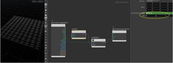
If you want to inspect intermediate results, press U to jump back to the upper level network and visualize point normals.
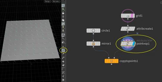
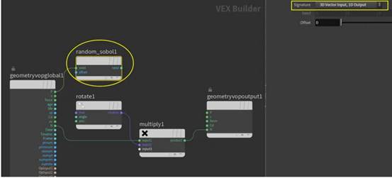
How do we generate random rotation angles inside point VOP? Add a random sobol node. Feed point position P as the seed. For Signature, select 3D Vector Input, 1D Output, because the input seed is a 3 dimensional coordinate and output is a 1 dimensional float value. The Offset acts as a shift value to modify random outputs. You can expose it as an external parameter for adjustment (see Note 012).
After obtaining random values ranging from 0 to 1, multiply them by 4 to expand the range to 0 4. Pass the result into a floor node for rounding down. For instance, an input value of 1.652 gets floored to 1. This converts continuous 0 4 float numbers into discrete integers 0, 1, 2, 3, each with equal 25 % probability.
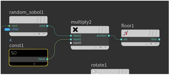
Multiply these integers by $PI*0.5 (equivalent to 90 degrees). The resulting angles (0°,90°,180°,270°) connect to the angle input of the rotate node.
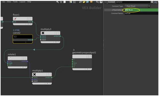
You will now see copied tiles with randomized rotations. Tweak the Offset parameter on the point VOP node to generate different Truchet variations.
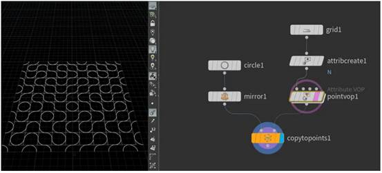
Proceed with post processing steps: resample the curves, fuse points, generate tubular geometry via polywire, and smooth surfaces with subdivide. These operations are straightforward.
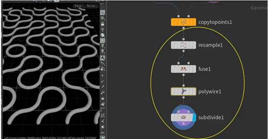
Finally, add random color per point attribute Cd using the attribute randomize node. Adjust RGB Min Value and Max Value to define your color range.